
Machining sealing faces right – the correct surface for every gasket
Overview for planners, maintenance managers and site supervisors: which surface finish suits which gasket, when the rough phonographic serration is required and when a smooth face, and which damage forces re-machining – mobile and on site to EN 1092-1 and ASME.
1 · Variety of forms & machining capacities
We flexibly adapt the mobile machine technology to the component – from the standard pipeline flange connection to the large, rectangular heat exchanger. The range covers almost all sealing-face forms:
Raised sealing face
Full face
Male & female
Tongue & groove
Ring-Joint (RTJ)
Lens gasket
2 · Which surface for which gasket?
The gasket determines the surface roughness – from rough (soft) to very fine (metallic). The following table lists the usual bands from gasket-manufacturer and ESA/FSA recommendations (as of 2026, without warranty).
| Gasket type | Rec. Ra | AARH (µin) | Surface / finish | Code |
|---|---|---|---|---|
| Soft-material gasket fibre, graphite, PTFE |
3.2–12.5 µm | 125–500 | rough, grooved („record/gramophone (phonographic) groove") – the soft gasket flows into the grooves and grips | ASME Stock EN B1 |
| Spiral-wound gasket (SWG) spiral-wound w. filler |
3.2–6.3 µm | 125–250 | medium – Stock or finer Smooth Finish; flatness particularly important | ESA/FSA |
| Metal-jacketed gasket double jacket w. soft filler |
1.6–3.2 µm | 100–125 | fine, smooth | ESA/FSA |
| Kammprofile / solid metal kammprofile, corrugated, solid |
≤ 1.6 µm | ≤ 63 | very fine / smooth – the metal teeth seal on a smooth surface | ESA/FSA |
| Ring joint (RTJ) / lens metal ring in the groove |
≤ 1.6 µm | ≤ 63 | very fine on the groove flanks; check against a reference sample | ASME B16.5 |
Standards framework, briefly explained
ASME B16.5 / B16.47: the groove (concentric or spiral) is turned with 30–55 grooves/inch. Stock Finish (standard) = 250–500 µin ≈ Ra 6.3–12.5 µm (1.6 mm round-nose tool); Smooth Finish = 125–250 µin ≈ Ra 3.2–6.3 µm. DIN EN 1092-1:2013: „turning" covers concentric or spiral grooves; Form B1 is the standard groove for all PN (Ra 3.2–12.5 µm), the finer Form B2 (Ra 0.8–3.2 µm) only by agreement. Ra/Rz are thereby assessed against reference samples – not measured directly on the sealing face.
- Needed for soft gaskets (soft material, partly spiral-wound gaskets): the rough, grooved surface gives the gasket „grip", it flows into the valleys and does not migrate (no creep).
- Not needed / rather smooth for metallic and kammprofile gaskets: here fine metal peaks seal on a smooth surface – a coarse groove would leave leak channels open.
- Concentric over spiral: a spiral groove is a continuous channel from inside to outside (leak path). Concentric grooves are closed rings and seal more reliably.
- Rule of thumb for medium/temperature: smooth/concentric for thin-flowing media and low temperatures, rougher at high temperatures.
Concentric groove
Spiral groove
3 · Flatness & parallelism
Semi-metallic gaskets in particular (spiral-wound gaskets) react sensitively to form errors. As a guide value from the ESA/FSA: flatness < 0.2 mm across the seating width, parallelism < 0.4 mm across the entire flange. Even the perfect gasket cannot compensate for a warped or uneven surface – here only re-machining helps.
4 · Damage patterns – when does re-machining become necessary?
The decisive question on site: is cleaning enough, or must the face be re-turned? This overview helps with identification – when in doubt, the WPS / project specification decides.
| Damage pattern | Why critical | How the practitioner spots it on site |
|---|---|---|
| Radial scores / scratches across the seating | direct leak path from inside to outside – cannot be reliably sealed with any gasket | scratches running across the groove (radially); a fingernail/coin edge catches; visible in raking light |
| Chatter marks / interrupted groove | uneven groove pattern → uneven surface pressure | „jumping", wavy or matt-shiny zones in the otherwise even groove pattern |
| Pitting / pitting corrosion, scars | localised leak points, destroyed groove pattern | dark spots/craters and rough scar fields, often on the medium side; check with a magnifier |
| Erosion / wash-out | material removal, seating becomes deepened or too narrow | shiny, washed-out track running in from the inner diameter |
| Dents / nicks / impact marks | local leakage, gasket does not bridge it | can be felt by hand; a straightedge shows a light gap at the spot |
| Warping / unevenness, lack of parallelism | gasket is pressed unevenly, tightening torque „fizzles out" | straightedge + feeler gauge: gap > 0.2 mm across the seating; light gap against the light source |
| Burnt-on gasket residue | gasket does not sit flat | discoloured, adhering deposits; always brush in the groove direction (never across) |
5 · Machining under real-world conditions & optimal preparation
Mobile machining rarely takes place under laboratory conditions – awkward positions, cramped pipe bridges or demanding materials (duplex, Inconel) are everyday reality. We match the procedure and tool selection to the real site situation. To keep downtimes short, you can prepare the site – everything is feasible, and we agree the exact procedure together in advance.
Checklist
If possible, remove bolts/nuts/studs (obstruction-free zone); roughly clean off old gasket residue.
Clearance around the component, stable scaffolding/anchor point at height; compressed air or power in the vicinity of the component (otherwise we work self-sufficiently, incl. lighting).
Prepare permits in good time (LOTO, hot work, confined-space entry) – then start right at the beginning of the shift.
Clarify the structurally permissible minimum flange thickness in advance through your engineering and let us know – we implement it to size and document it.
6 · Welded Sealing Connections: Welded Lips, Profiles & Membranes
Where the medium is particularly hazardous or an operational shutdown must be avoided at all costs, an inserted gasket is replaced by a welded, metallic sealing connection – the „absolutely safe“ connection with a leakage rate of practically zero. It is only conditionally releasable: to open it, not only are the flange bolts loosened, but the seal weld is additionally cut open. The sealing rings are made of the same or a closely related material as the flange or pipe and are always used in pairs (A series profiles per DIN 2695, if required flange form M per DIN 2526).
| Profile | Cross-section | Sealing principle |
|---|---|---|
| A23 | 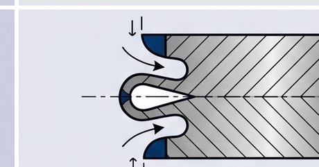 | Labyrinth seal (non-contact) |
| A24 | 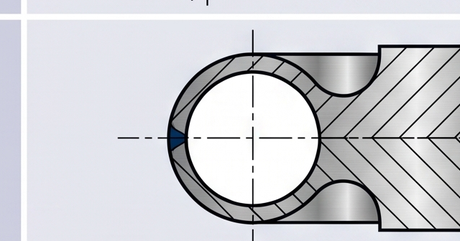 | Pressure-activated tube seal |
| A24H | 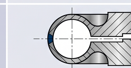 | Pressure-activated, stepped support |
| A24K | 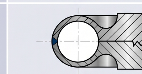 | Pressure-activated, toothed support |
| A25 | 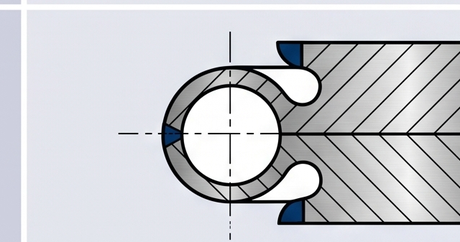 | Split pressure lips |
Profiles & Sealing Principle
Two basic designs are distinguished: the flat membrane (profile A21) and the resilient hollow-lip or Omega profiles (A23–A25) with a formed torus. The hollow lip creates better stress distribution in the seal weld and accommodates radial differential expansion up to Δr ≈ 5 mm; the internal pressure additionally supports the lip (pressure-loaded lip). For this reason, A24/A25 are the first choice for heat exchangers with differing expansion behaviour, e.g. between the channel-cover flange and the tube sheet. For special requirements regarding support of the lip, there are variants such as A24H (crowned sealing face) and A24K (comb (serrated) profile with a soft facing).
Attachment Weld, Seal Weld & Reuse
The attachment weld joins one weld half to the flange (inside, outside or both), the seal weld welds both rings together. Depending on the material and profile, a connection is re-weldable 2 to 5 times; with each opening, some material is lost through the cutting. For the sealing faces, a surface roughness of Rz ≈ 25–50 µm typically applies; optionally, an auxiliary gasket can be provided for the pressure test or start-up phase.
Membrane / Diaphragm Seals – the HSOS Special Process
A diaphragm (membrane) is a round metal plate that is welded directly onto the sealing face with a circumferential fillet weld and fully covers the flange opening – creating a hermetic, media-side closure entirely without an inserted gasket. There is no inner weld seam: it is opened by machining off the fillet weld again and then cleanly restoring the sealing face – conventionally a tricky, time-consuming step.
Sources & standards
Frequently Asked Questions
Does the flange have to be removed for machining?
No. We install the machine tools directly on the component and restore the sealing face on site – saving dismantling, transport and downtime.
Which flange sizes and shapes can be machined on site?
Internal-clamping 15–12,000 mm, external-clamping 0–1,700 mm machining diameter. Besides round flanges also oval manways and large rectangular components, plus RTJ grooves and lens-gasket seats.
Which surface roughness goes with which gasket?
Soft gaskets need a rough, serrated face (Ra 3.2–12.5 µm), spiral-wound medium (3.2–6.3 µm), metal-jacketed fine (1.6–3.2 µm), camprofile and RTJ gaskets very fine (≤ 1.6 µm). Your WPS governs.
When is the phonographic (serrated) finish required – and when not?
Soft gaskets need the serration because they bite into it; metallic gaskets need a smooth face. Concentric grooves seal more reliably than spiral ones, which form a leak path from inside to outside.
Which damage makes re-machining necessary?
Above all radial scratches crossing the seating face (impossible to seal with any gasket), warping/non-flatness, pitting/corrosion, chatter marks and erosion. The depth limits in ASME PCC-1 Appendix D serve as a guide.
Can I read the permissible minimum flange thickness from the standard tables?
No. DIN EN 1092-1 and ASME B16.5 only give new-part nominal dimensions. The repair limit depends on your operating data and must be released by your engineering department or an authority – we keep to it precisely and document it.
To which standards do you produce the surface?
Exactly to your project specification/WPS – to DIN EN 1092-1 (form A/B1/B2) as well as ASME B16.5/B16.47 (stock or smooth finish, phonographic serration); for RTJ/lens the required fine roughness.
Do you also machine welded lip and membrane / diaphragm seals?
Yes. We open welded lips with special machines (cutting open the seal weld and re-bevelling the lip) and restore the sealing face. For membrane / diaphragm seals we have our own CNC-controlled process that is safer and faster than conventional methods and is protected by a registered utility model (DE 20 2025 102 197).